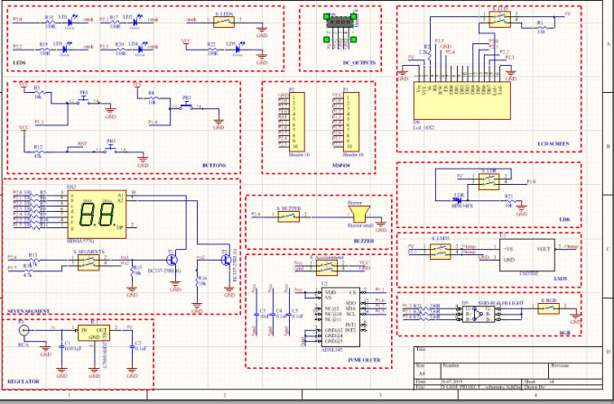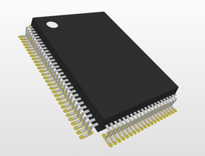

etc.,) are collectively stored in a Schematic Library file ( *.SchLib) that can be loaded in CircuitStudio. Schematic component definitions (composed of a symbol, model links, parameters. In CircuitStudio, this schematic representation of the component also provides a range of optional properties, parameters and links to a PCB footprint pattern – or more correctly, a 2D and/or 3D model that physically represents the component on a PCB. The initial task in this part of the design process is generally capturing its circuitry in a schematic, where a placed component provides a graphical symbol that includes the component’s electrical connection points defined by pins. Components are ‘wired’ together to form the complete design. In its common form, a component is generally composed of a logical symbol that is applied to the design’s schematic and a footprint pattern (model) that will physically represent the component on the PCB.

This connector cannot be created automatically using the IPC Compliant Footprint Wizard, so it must be created manually using the recommended PCB layout view from the datasheet.A component is the general name given to a part that can be placed into an electronic design during the design capture process.

If you have closed the tab with this component, search for it in the Components panel, right-click on its name then select Edit. Let’s create a footprint for the GSB343K33HR component whose symbol was created in chapter 5.1. In Altium Designer, the process of creating footprints is simple, convenient and protected from errors as much as possible. Any error in the placement of the footprint pads can lead to problems, up to and including the inability to assemble the final device, so library designers should be very careful while creating footprints. Also, the component itself will be soldered onto these contact points, so their configuration should be fully consistent with the actual metal objects of the component. Component footprints contain a set of graphical primitives and copper pads or holes that will be connected to the conductors and will provide a connection. The next step in creating the component is to design the footprint.


 0 kommentar(er)
